Omron PLC Serial Interface
- Download Omron-App.zip - 32.76 KB
- Download Omron-Labview.zip - 342.4 KB
- Download OmronHostLinkUnit - 768.82 KB
- Download TimeAverage-30Words-En - 11.97 KB
- Download TimeAverage-60Words-En - 25.06 KB
Introduction
If you're tired of using some complex non-realtime COM/COM+ components (as I'm ;D) that force you to connect Omron PLC series and are interested in an easy understanding, open source, real real-time .NET based object, you've just selected the right article.
This article introduces a purely code-based Host link protocol implementation, what you can easily add into your project ensures you a safe reliable RS232/485 PC-PLC communication.
Background
OOP programming and using an accurate implementation in realtime hardware dependant is something I've done once in DeltaDTB PID Controller. You can refer to it from here.
Using the Code
1. Wiring
With no doubt, the most confusing matter one may face, after reading the PDF file reduced from Omron describing the Host Link attributes, is physical connection (cable wiring). After first perusing, I made some wiring hoping it would work, but there was no success despite all my efforts. Finally, the old popular RS232 (2-2, 3-3, 5-5) was the thing answered properly (look at the below picture).

2. Communication Protocol
2.1 Basic Definitions
- Host Computer
In host link communication protocol, the host computer (please note Omron refers to "computer" for its PLC series, please don’t mix up!) has the transition priority, but for the case of peer to peer connection (e.g. you directly connected to a PLC via RS232 physical layer) noting this matter is not very important, but if you’re very sensitive and scrupulous about, due to Omron definition "Data transfer between the host computer and the Host Link System is, therefore, initiated when the computer sends a command to a PC in the Host Link System." (part 3-2, Communication Protocol, page 62), the PC which runs the application assumed as Host Computer.
- Block
A set of data in a transmission is called a block.
- Command Block
The data block sent from the host computer to the Host Link System is called a command block.
- Response Block
The block sent from the Host Link System to the computer is called a response block.
- Multiplex Communication versus Single Link Communication
In a multiple-link communications system, each block starts with a unit number and a header, and ends with a Frame Checksum (FCS) code and a terminator (* and CR). In a single-link system, however, each block starts with only a header, and ends with only a terminator.
- Termination
The terminator in the command block enables the PC to send a response. The terminator in the response block enables the host computer to send another command.
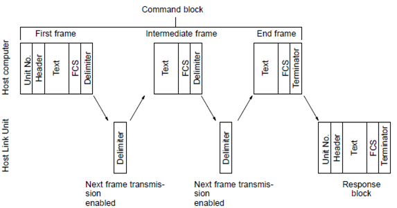
2.2 Block Formation
Below is a scheme of a formal data block. A block is usually made up of one unit called a frame, but long blocks of data (over 131 characters) must be divided into more than one frame before transmission. In a multiple-link system, the first frame can have up to 131 characters, and subsequent frames can have up to 128 characters.
In a single-link system, however, every frame (the first included) has up to 128 characters. The data must then be divided into more than one frame when there is a block consisting of more than 131 characters in a multiple-link system and of more than 128 characters in a single-link system. In this case, the beginning and intermediate blocks end with a delimiter (CR), instead of a terminator (* CR).
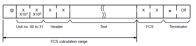
Note: In this project, Multiple-link System is assumed as in-use method, so, inserting "@" and unit number is mandatory and done automatically when requests for reading/writing is demanded.
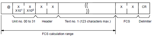
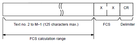
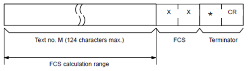
2.2.1 Block Formation with more than one frame in Multi-Link System
First Frame (131 characters or less)
Intermediate Frame(s) (128 Characters or less)
Last Frame (128 characters or less)
2.3 Sending Commands
To send a command block with more than one frame from the computer (host computer), initially send only the first frame in the block. We must wait for sending the next frame until the host computer has received the delimiter which should have been sent back from the PC.
Note: Do not separate data from a single word into different frames for any write command.
The best place of use is when you try to write a long stream of data in a sequence of registers (although I don't advice this matter).
...
Do
    Do
        str_in = str_in & Link.ReadExisting
    Loop While ((str_in.Length < length_predicted) And _
	((DateAndTime.Now.Ticks - tmr_indicator) < lng_length))
    ....
    'Checking FCS code
    'Checking PLC Response code (No Command Error)
    ...
    'Assume we're waiting for frame(s)
    'The matter that must be checked is the penultimate and the last
    'character received from PLC.
    if mid$(str_in,str_int.length - 1,1)<>"*" then 	'Means some frame(s)
						'are ready to be received
        'First Process Data
        'Clear RS232 Input Buffer
        str_out = Link.readExisting
        'str_out = ""
        link.Write(vbCr)'Indicates Host Computer is ready to receive data
        ...
    end if
    ...
Loop While loop_condition
...
2.4 Receiving Commands
To receive a response block consisting of more than one frame from the PC, the host computer must send the carriage return code (delimiter) to the PC after receiving the delimiter from the PC. This enables the PC to send the next frame.
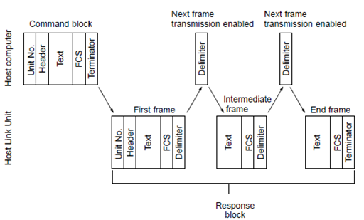
Its obvious usage is in Read method, where for example, the user's demanded reading a more 30 consequence registers. After making the string indicates from what address and how many register(s) user requested, we entered a loop waiting for PLC response. Don't forget it's essential to keep the requested numbers in a variable.
Dim loop_count As Integer = 0, count_predicted As Integer = 0,
_As Long = 0, tmr_indicator As Long = 0,
_As Integer = 0
Dim str_in As String = "", str_in_final As String = ""
str_in = Link.ReadExisting()
str_in = ""
Link.Write(str_out)
Do
    str_in = ""
    count_predicted = IIf(count > 30, 30, count)
    If loop_count = 0 Then
        If count_predicted = count Then
            length_predicted = count_predicted * 4 + 11
        Else
            length_predicted = count_predicted * 4 + 10
        End If
    Else
        If count_predicted = count Then
            length_predicted = count_predicted * 4 + 4
        Else
            length_predicted = count_predicted * 4 + 3
        End If
    End If
    lng_length = (length_predicted * ByteTime * 1000) + delay_ms
    lng_length *= TimeSpan.TicksPerMillisecond
    tmr_indicator = DateAndTime.Now.Ticks

    Do
        str_in = str_in & Link.ReadExisting
    Loop While ((str_in.Length < length_predicted) And _
	((DateAndTime.Now.Ticks - tmr_indicator) < lng_length))

    If ((loop_count > 0) And (str_in.Length < length_predicted)) _
	Then Throw New OmronException("Error in Data line, Data corrupted!")

    If loop_count = 0 Then 'Indicates first frame

        p_response = Hex2Int(Mid$(str_in, 6, 2))

        If Mid$(str_in, str_in.Length, 1) <> vbCr Then _
	Throw New OmronException("Error in Data line, Data corrupted!")

        If Not (FCSCode_Get(str_in)) Then Throw New OmronException_
	("Comminucation Error, Please check the line!")If p_response <> _
	Omron_Response_Code.Command_Completed_Normally Then _
	Throw New OmronException(Response(p_response)(0))

        If count_predicted = count Then 'One block contains the whole response
            str_in_final = str_in_final & Mid$(str_in, 8, str_in.Length - 11)
        Else 'It's the first block of a sequence of response blocks
            str_in_final = str_in_final & Mid$(str_in, 8, str_in.Length - 10)
        End If
    Else
        If count_predicted = count Then 'Indicates last frame
            str_in_final = str_in_final & Mid$(str_in, 1, str_in.Length - 4)
        Else 'Indicates intermediate frame
            str_in_final = str_in_final & Mid$(str_in, 1, str_in.Length - 3)
        End If
    End If

    str_in = Link.ReadExisting
    if count_predicted < count then Link.Write(vbCr)
    str_in = ""

    count = IIf(count - 30 > 0, count - 30, 0)
    loop_count += 1

Loop While count > 0
2.5 Data Representation
Unit Address, Register Address and number of registers to be read must be represented in Decimal format, Register contents which to be read/written must be presented in hexadecimal format and Boolean is represented as "1" (ASCII 49dec)(true) and "0" (ASCII 48dec)(false).
2.6 Frame CheckSum (FCS) Calculation
The Frame Checksum is 8-bit data converted into two ASCII characters. The 8-bit data is the result of an EXCLUSIVE OR sequentially performed between each character, from the first character in the frame to the last character of the text in that frame.
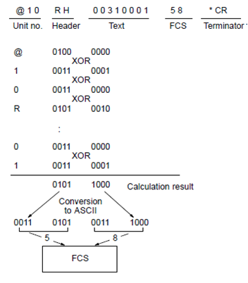
Dim [xor] As Integer = IIf(is_last, 0, 64) '@ascii code
For I As Integer = 1 To Message.Length - 1
    [xor] = [xor] Xor Convert.ToInt32(Convert.ToChar(Message.Substring(I, 1)))
Next
Return ([String].Format("{0:X}",[xor]))
The FCS generator piece of code is mentioned above.
3. Command Level
The tables on pages 60 to 62, give the commands and responses available for the Host Link Units, the command levels, and the modes in which they are applicable. Details of the command and response formats are given in Omron Document, Section 4 Commands and Responses.
Using the Demo, Step by Step
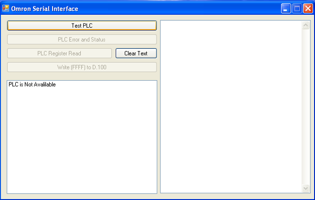
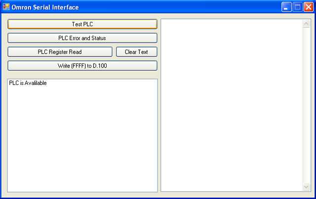
3.1 Running the program
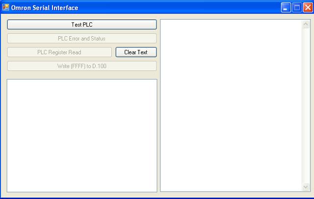
3.2 Checking whether any PLC is connected or not
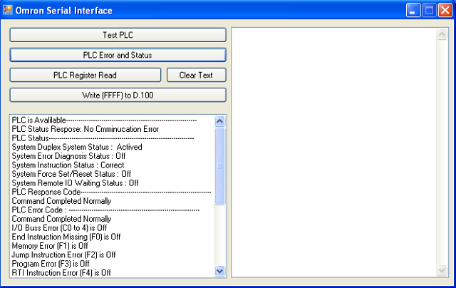
3.3 Reading PLC Status and Errors
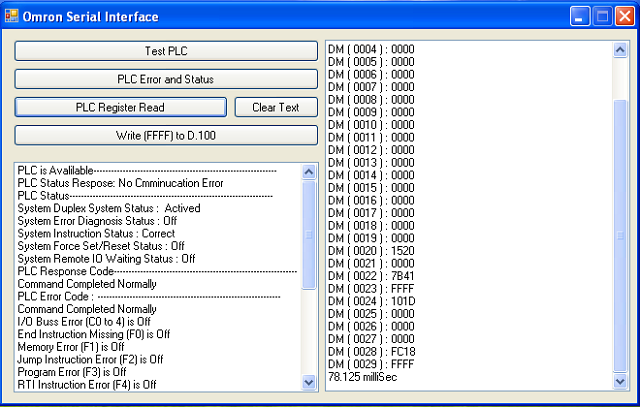
3.4 Reading 30 sequence Registers from PLC
Acknowledgements
It's my appreciation to thank Prof. Kamalaldin Farzaneh, who is not only my manager, but also my teacher who has let me test, fall and rise again.
History
- Creation Time: Wednesday Apr 27 2011
- First Release: Saturday Apr 30 2011
- Updated: Tuesday May 03 2011
- Updated: Sunday July 24 2011, Labview 7.0 Implementation added
 "
"发表评论
 best pron[37.233.27.*]2017/11/8 23:43:14#12
JJXTS4 Wow, fantastic blog layout! How long have you been blogging for? you made blogging look easy. The overall look of your site is fantastic, as well as the content!
ZmRxXo more at Voice of America (blog). Filed Under:
9NV8G0 Thanks so much for the article.Really looking forward to read more. Really Cool.
Really informative post.Thanks Again. Cool.
UBKdid It`s really useful! Looking through the Internet you can mostly observe watered down information, something like bla bla bla, but not here to my deep surprise. It makes me happy..!
QGSAeH I think the admin of this site is genuinely working hard
elzkxd
EBBl2h Im thankful for the article post.Really thank you! Awesome.
adderall abuse essay - adderall side effects numbness
buy valium online in canada - buy valium london
hsPMax Thanks so much for the post.Really thank you! Want more.
uPYQ26 Very neat article post.Much thanks again. Cool.